
TM 5-3820-276-10-2
0148
LOW OR NO FLOW FROM PUMP DISCHARGE - GROUTER - Continued
CORRECTIVE ACTION - Continued
2.
Attempt to discharge from grouter output (Volume 1, WP 0040).
a.
If discharge is normal, problem solved.
b.
If discharge remains low or not present, proceed to next MALFUNCTION - Grout pump(s)
require reset.
MALFUNCTION
Grout pump(s) require reset.
CORRECTIVE ACTION
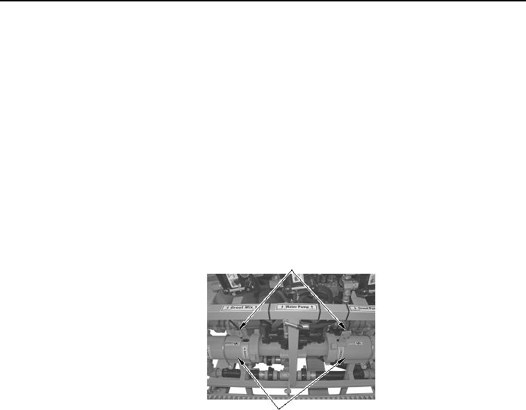
Observe proximity switches and verify if one or both grout pumps is stuck (not pumping)
(Figure 2).
PROXIMITY SWITCHES
GROUT PUMPS
WWDS00407
Figure 2.
Grout Pumps and Proximity Switches.
a.
If one or both grout pumps are not operating, reset grout pump(s) by operating in manual
mode (Volume 1, WP 0040). Verify if discharge from grouter output is normal (Volume 1,
WP 0040). If both grout pumps do not operate, proceed to next MALFUNCTION - Grout
pump fuse unserviceable (blown).
b.
If both grouter pumps are operating but output remains low, notify maintenance.