• Home
  • Download PDF
  • Order CD-ROM
  • Order in Print
Figure 8. Main Power Control Switch
Figure 10. Discharge Air Pressure Gauge.

Technical Manual For Water Well Drilling System (Wwds) - 1 Page Navigation
  616    617    618    619    620  621  622    623    624    625    626  
img
.
TM 5-3820-276-10-1
0059
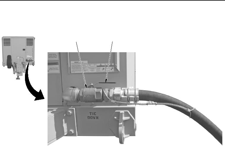
PAC SHUTDOWN PROCEDURES - Continued
3.
Rotate handle (Figure 9, Item 2) on air service valve (Figure 9, Item 1) to Open position.
2
1
WWDS00419
Figure 9.
Air Service Valve (Shown Open).
4.
Check DISCHARGE AIR PRESSURE gauge (Figure 10, Item 1) to make sure automatic blowdown valve
opens, releasing pressure from receiver tank.
0059-10
02/13/2013root(opusualwp)wpno(O30009)


Privacy Statement
Press Release
Contact

© Copyright Integrated Publishing, Inc.. All Rights Reserved.