TM 10-5430-245-13&P
0005 00
a.
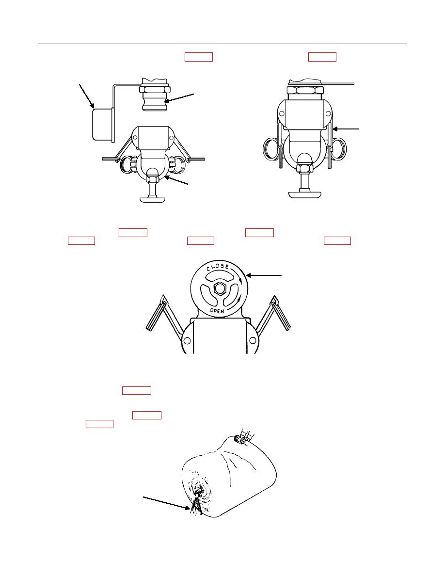
At one end of the drum, remove dust cap (Figure 1, Item 1) from adapter assembly (Figure 1, Item 2).
1
2
4
3
b.
Slide coupler valve (Figure 1, Item 3) onto adapter assembly (Figure 1, Item 2). Lock coupler valve
(Figure 1, Item 3) onto adapter assembly (Figure 1, Item 2) by pushing in the cam arms (Figure 1, Item 4).
1
c.
Turn the handwheel (Figure 2, Item 1) counterclockwise all the way to completely open the coupler valve (one of
the two coupler valves that comes with the drum).
d.
Fully collapse the drum (Figure 3). Push down on drum to squeeze air out. Trapped air will rush out of the coupler
valve (Figure 1, Item 3).
AIR


