TM 10-4630-207-13&P
0023 00
4
2
2
1
3
5
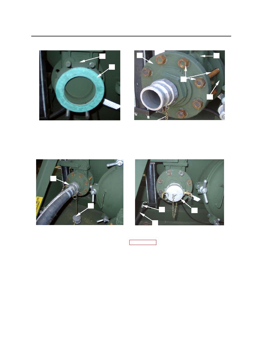
Figure 7. Installing Front Gasket and Flange
17. Install dust cap (figure 8, item 1) or 2-inch hose (figure 8, item 2) as appropriate.
18. Re-connect the intake valve hydraulic line (figure 8, item 3) to the fitting (figure 8, item 4) on the
piston valve.
2
1
4
1
3
Figure 8. Installing Dust Cap/Hose and Hydraulic Line
19. Refill and bleed hydraulic system as described in WP 0025 00.
END OF WORK PACKAGE
0023 00-6


