
TM 10-4630-207-13&P
0005 00
3
1
4
2
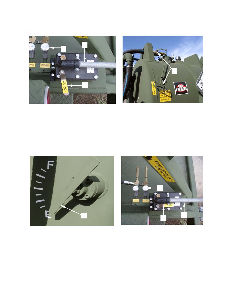
Figure 34. Hydraulic Valve Controls and Isolation Valve
e. Observe tank draining as shown on float level indicator (figure 35, item 1).
f.
When tank is empty, close drain valve (DISCHARGE) hydraulic control knob (figure 35, item 2).
g. Place hydraulic pump selector lever (figure 35, item 3) so it is aligned with the pump handle
(figure 35, item 4).
2
4
1
3
Figure 35. Float Level Indicator and Hydraulic Valve Controls
h. Proceed to step 9.
0005 00-21
