TM 10-4630-207-13&P
0005 00
2
1
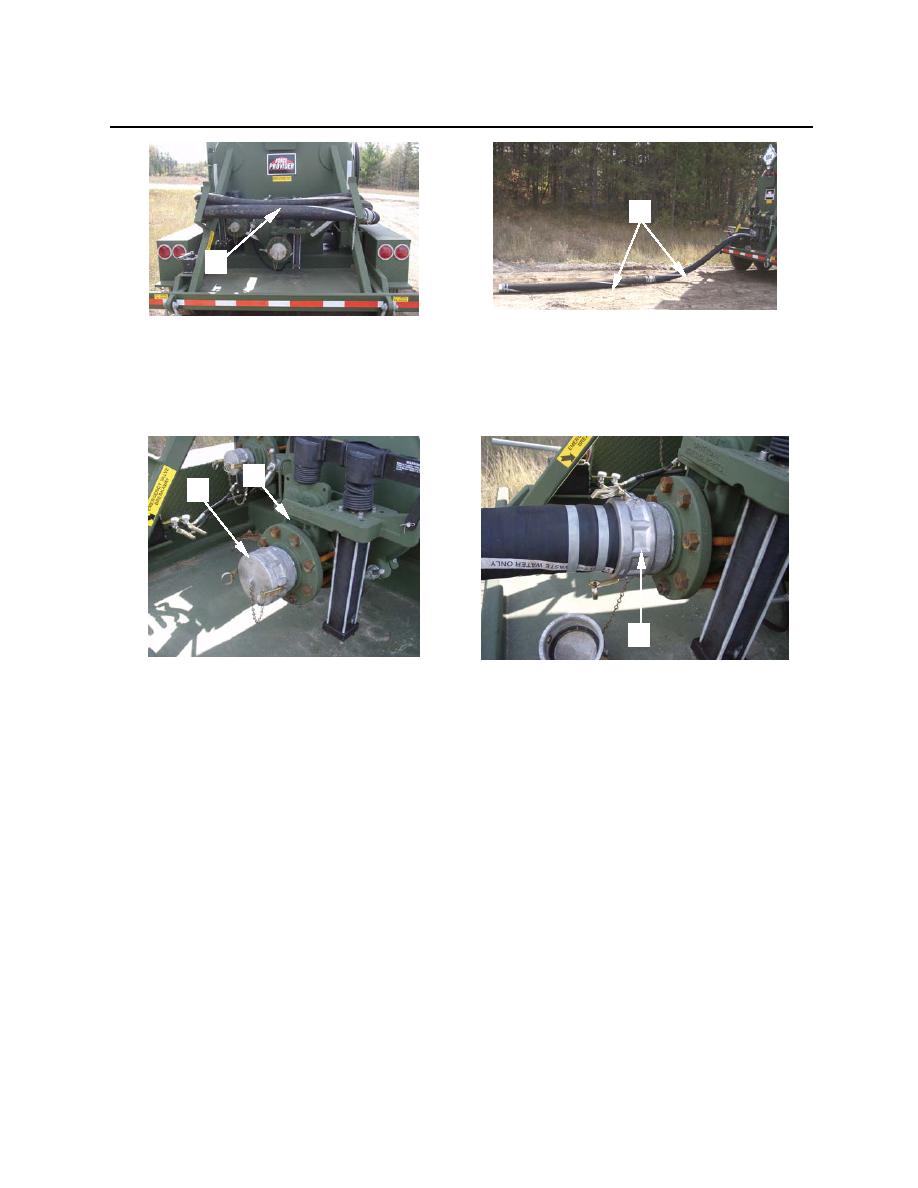
Figure 32. Drain Hose Removal and Assembly
4. Remove dust cover (figure 33, item 1) from drain valve (figure 33, item 2). Connect the female cam-
lock of one 4-inch drain hose (figure 33, item 3) to the drain valve.
2
1
3
Figure 33. Drain Hose Connection
5. Connect or place the other end of the assembled drain hoses to/into the designated disposal point.
6. If tank is to be drained by gravity, proceed to step 7. If tank is to be drained under pressure, proceed
to step 8.
7. To drain tank by gravity, proceed as follows:
a. Open the drain valve (DISCHARGE) hydraulic control knob (figure 34, item 1).
b. Place hydraulic pump selector lever (figure 34, item 2) so it is pointing away from the pump
handle (figure 34, item 3).
c.
Operate hydraulic hand pump (figure 34, item 3) until drain valve fully opens.
d. Open the isolation valve (figure 34, item 4).
0005 00-20


