
TM 10-4630-207-13&P
0005 00
2
1
1
3
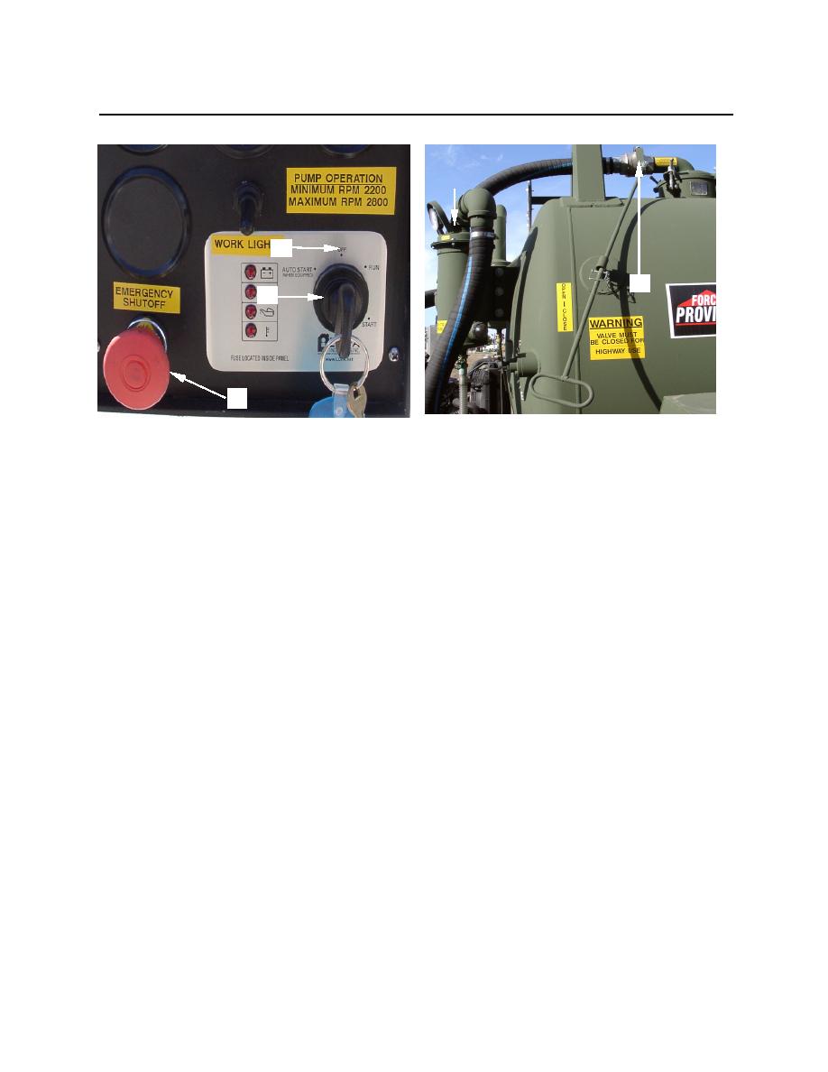
Figure 25. Control Panel
Figure 26. Isolation Valve
26. Disconnect 2-inch intake hose (figure 27, item 1) from intake valve (figure 27, item 2) and drain
into source.
27. Disconnect 2-inch intake hoses from each other and the chopper tube/wand. Flush hoses with
freshwater. Place hoses onto hose hooks (figure 28, item 2) and ends into the equipment trays.
28. Place chopper tube/wand with the PVC ball valve (figure 22, item 1) open, into one of the equipment
trays. Install dust cover (figure 29, item 2) on intake valve (figure 29, item 1).
0005 00-16
