
TM 10-4630-207-13&P
0005 00
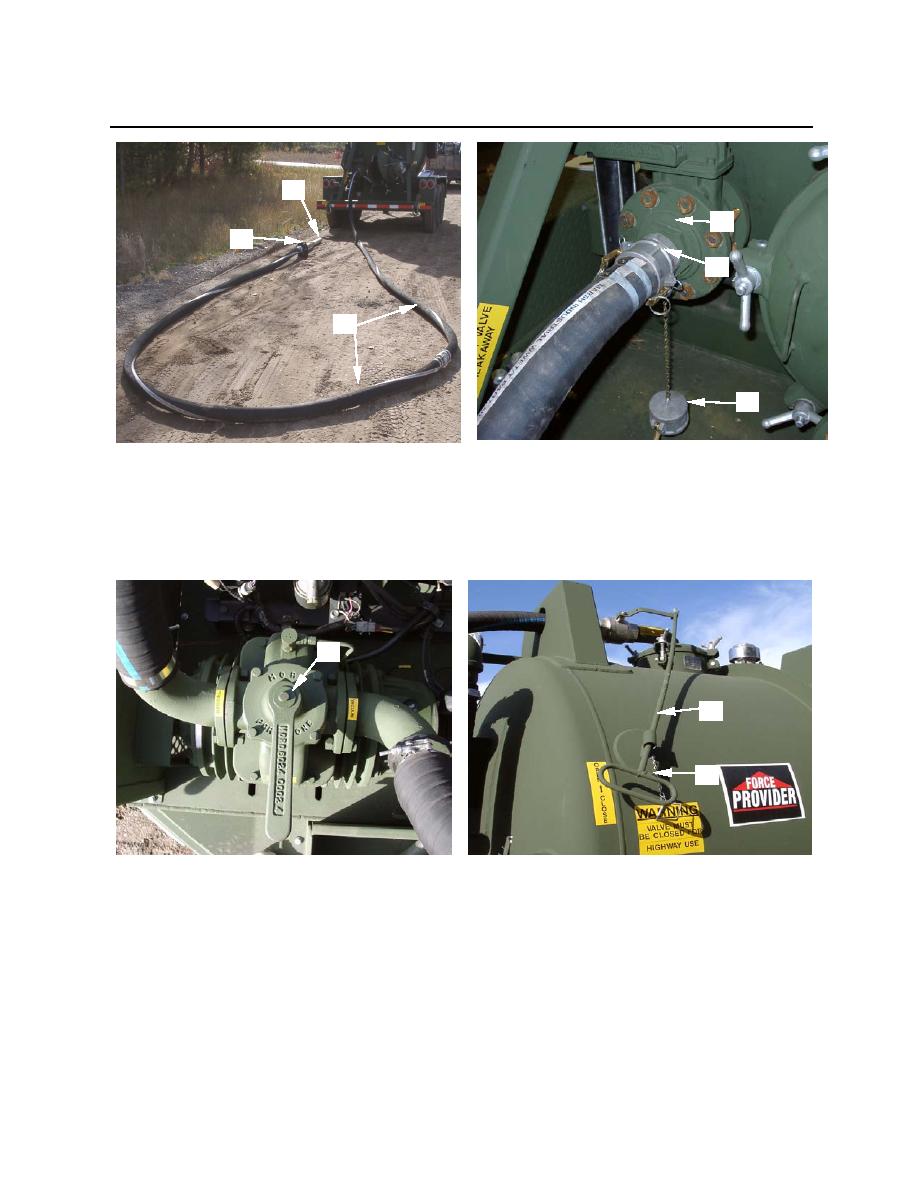
2
5
3
6
1
4
Figure 14. Assembling Intake Hoses
5. Place vacuum pump control handle (figure 15, item 1) in neutral position.
6. Remove pin (figure 16, item 1) and place isolation valve (handle) (figure 16, item 2) in the OPEN
position (in line with hose).
1
2
1
Figure 15. Vacuum Pump Control
Figure 16. Isolation Valve Control
7. Close drain valve on moisture trap (figure 17, item 1) and oil catch muffler (figure 18, item 1).
0005 00-11
