
TM 10-4630-207-13&P
0005 00
2
1
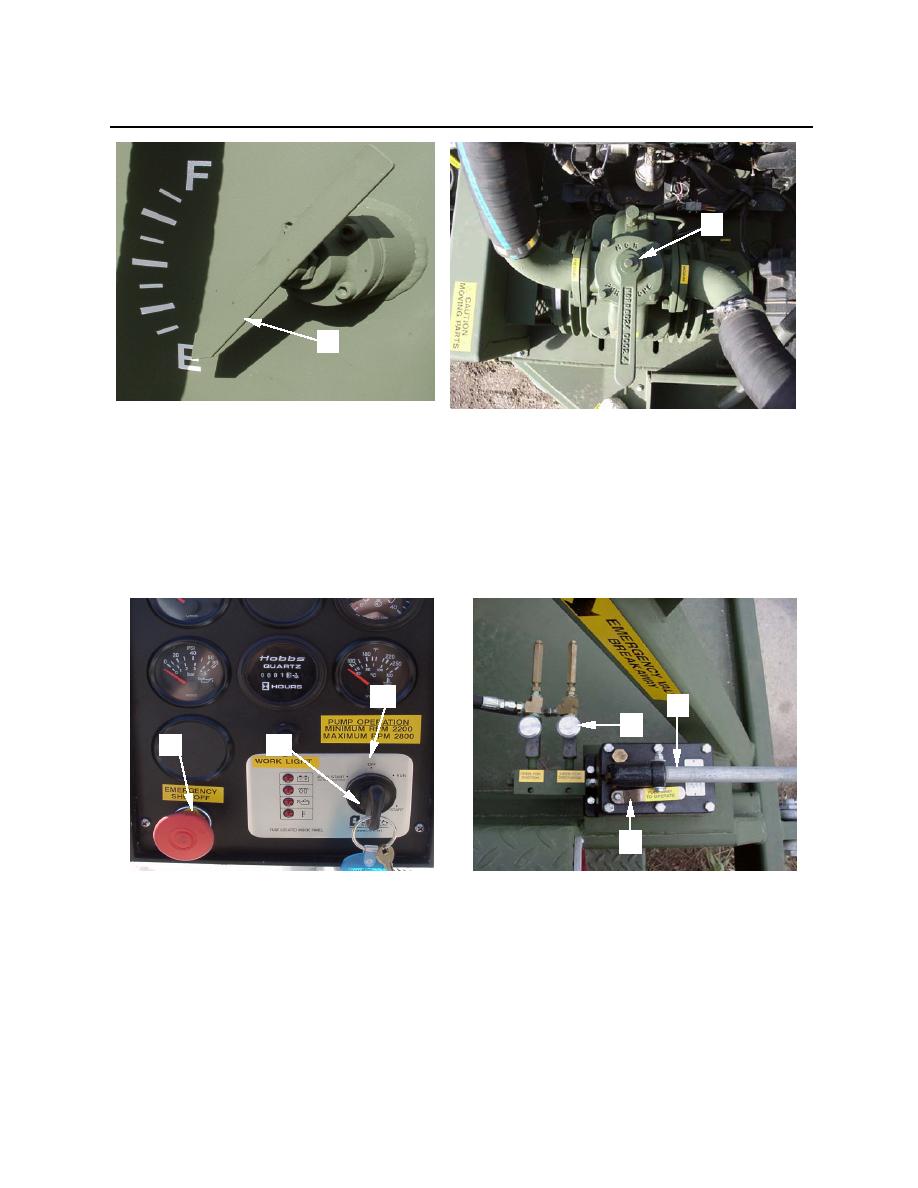
Figure 39. Float Level Indicator and Vacuum Pump Control
n. Close drain valve by placing hydraulic pump selector lever (figure 40, item 3) parallel with pump
handle (figure 40, item 4).
o. Shut down diesel engine by turning ignition key (figure 40, item 1) to the OFF position (figure
40, item 2). Remove key and push in emergency shutoff button (figure 40, item 6).
p. Close drain valve (DISCHARGE) hydraulic control knob (figure 40, item 5).
2
4
5
6
1
3
Figure 40. Control Panel and Hydraulic Valve Controls
9. Disconnect assembled 4-inch drain hose (figure 41, item 1) from drain valve (figure 41, item 2).
Install dust cover (figure 41, item 3) on valve. Drain assembled 4-inch x 10-foot hoses into the
designated disposal point.
10. Clean and sanitize hoses by flushing with fresh water and draining in accordance with local
regulations and Unit SOP. Dispose of waste in an approved treatment system or waste disposal site
in accordance with host nation, local, or unit procedures designed to protect human health and the
environment.
0005 00-24
