TM 10-4320-344-24
3.8.11 Fuel Injection Pump Assembly Maintenance, Models 609-C and US636HCCD-1.
(Continued)
If top dead center (TDC) and fuel injection point are marked on
crankshaft pulley, perform step a and proceed to step s.
Cylinders are numbered from flywheel end of engine.
a .
Place pan under FIP assembly and turn crankshaft until number 1 cylinder is at
TDC.
If TDC and fuel injection point are not marked on crankshaft pulley, perform
steps b through r to determine TDC and fuel injection point.
b .
c .
d.
e .
Turn crankshaft until valves on cylinder number 1 overlap.
Mount setting device (Figure 3-26, 1).
Depress rocker arm (2) 0.197-0.236 inches (5-6 mm).
Mount dial indicator (3) on setting device (1) and preload.
f .
g .
h.
i .
j .
k .
l .
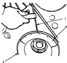
Figure 3-27.
Pointer and Graduation Magnet
Attach pointer (Figure 3-27, 1) to dowel sleeve.
Installation.
Attach graduation magnet (2) to crankshaft pulley (3).
Align 0 on graduation magnet (2) with pointer (1).
Turn crankshaft slowly to the right until depressed valve (Figure 3-26, 2)
moves upward.
Continue turning crankshaft until pointer on dial indicator (3)
starts to change direction.
Stop turning crankshaft.
Set dial indicator (3) to 0.
Turn crankshaft to the left until pointer of dial indicator (3) completes one
revolution and dial indicator (3) reads 0.004 inches (0.1
Record the crankshaft position from the graduation magnet
indicated by the pointer (1).
mm) from 0.
(Figure 3-27, 2) as
3-68