TM 10-4320-344-24
2.21.49 Rocker Arm (Valve) Adjustment, Model 609-A.
This task covers:
2.21.49.1
Cold
Engine
Valve
2.21.49.2 Warm Engine Valve
Adjustment
Adjustment
INITIAL SETUP
Tools
General Safety Instructions
General Mechanic’s Automotive
Do not work on equipment that is not
Tool Kit, Appendix B, Section
securely stabilized to prevent rolling
III, Item 1
o r s l i d i n g.
Equipment Conditions
Do not work on equipment without follow-
ing standard shop safety practices.
Pumping station shut down, TM 10-4320-
344-10.
Cylinder Head Cover removed, paragraph
2 .
2
1 .
4
7.
(Cold Adjustment Only.)
2.21.49.1 Cold Engine Valve Adjustment.
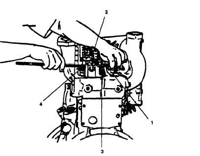
Figure 2-164.
Valve Adjustment, Model 609-A.
Cylinder is at top dead center (TDC) when both intake and exhaust valves are
f u l l y c l o s e d.
a .
Rotate crankshaft until cylinder no. 1 is at TDC.
b .
Insert 0.016-0.017 (0.4-0.425 mm) feeler gauge (Figure 2-164, 1) between
rocker arm (2) and intake valve stem (3).
c .
Adjust setting screw (4) until rocker arm (2) just touches feeler gauge (1).
2-368