TM 10-4320-344-24
2.21.8 Fuel Injection Nozzle and Holder Assembly Maintenance. Model 609-A.
This task covers:
2.21.8.1
Removal
2.21.8.3 Installation
2 .
21 . 8 . 2 T e s t
INITIAL SETUP
Tools
General Mechanic’s Automotive
Tool Kit, Appendix B, Section III,
Item 1
Goggles, Appendix B, Section III, Item 2
Gun, Air Blow, Appendix B, Section III,
Item 2
Torque Wrench, Appendix B, Section 111,
Item 2
Static Fuel Nozzle Testing Fixture,
Appendix B, Section III, Item 5
Material/Parts
Diesel Fuel, Appendix C, Item 10
Rags, Appendix C, Item 20
Materials/Parts (Continued)
Tags, Appendix C, Item 31
Gaskets (TM 10-4320-344-24P)
Lock Washers (TM 10-4320-344-24P)
Equipment Conditions
Fuel Leakoff Manifold Assembly and Fuel
Injection Lines disconnected and capped,
paragraph 2.21.7.
General Safety Instructions
Diesel fuel is flammable.
Keep sparks,
cigarettes, and open flame away from fuel
system components.
Do not work on equipment without
following standard shop safety
precautions.
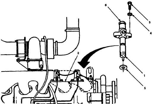
2.21.8.1 Removal.
Figure 2-121.
Fuel Injection Nozzle end Holder Assembly Removal, Model 609-A.
2-279