TM 10-4320-344-24
2.21.6 Fuel Transfer Pump Assembly Maintenance. (Continued)
c .
Start engine, refer to TM 10-4320-344-20.
d .
Check to see if fuel is being forcefully ejected from fuel transfer pump
assembly (1).
Pressure output from fuel transfer pump assembly is 3-5 psi (20-34 kPa).
e .
If fuel is not being forcefully ejected from fuel transfer pump assembly (1),
service fuel transfer pump assembly (1).
f .
Stop engine, refer to TM 10-4320-344-10.
g-
Remove pan from under fuel transfer pump assembly (1) and properly dispose of
fuel in accordance with standing operating procedures.
2.21.6.3 Removal.
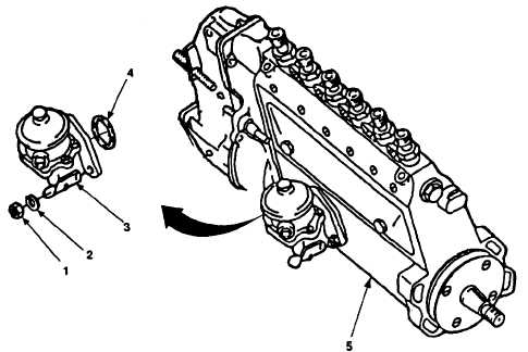
Figure 2-119.
Fuel Transfer Pump Assembly Replacement (Model US636HCCD-1 Shown).
a .
Place pan under engine.
b .
Remove three nuts (Figure 2-119, 1), lock washers (2), fuel transfer pump
assembly (3), and gasket (4) from fuel injection pump assembly (5. Discard
gasket (4).
2.21.6.4 Assembly.
Torque mounting nuts for Model 609-A to 15
a.
Install new gasket (4) and position fuel transfer
injection pump assembly (5) and secure with three
n u t s ( 1 ).
b .
Remove pan from under engine and properly dispose
standing operating procedures.
2-276
ft-lbs (20 N•m).
pump assembly (3) on fuel
new lock washers (2) and
of fuel in accordance with
NOTE
NOTE