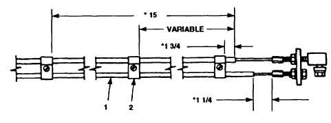
Figure 2-46.
Sheathing and Cable
g .
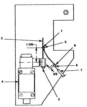
Install universal wire stop (Figure 2-47, 1)
inches from center of pivot arm (3) on limit
universal wire stop (l).
Clamp Positioning.
on wire (2) approximately 1 3/8
switch (4).
Tighten screw (5) on
h.
Install universal wire stop (6) on power control cable assembly (7)
approximately 3/8 inch from power control cable assembly (7) end.
Tighten
screw (8) on universal wire stop (6).
Figure 2-47.
Power Control Cable Assembly Installation.
2-129
TM 10-4320-344-24