TM 10-4320-315-24
3-19. MAINTENANCE OF ALTERNATOR - (Cont)
Figure 3-18. Testing Diodes
(3)
Test rotor as follows:
(a)
Using multimeter, check winding resistance across slip rings.
(b)
Multimeter should indicated 8.5 to 11 ohms resistance; if not, replace rotor assembly.
e. ASSEMBLE.
(1)
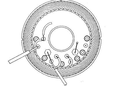
Solder three wire leads of stator assembly (13, Figure 3-17) to diode assembly (27).
(2)
Install seal (28) on diode assembly (27).
(3)
Install diode assembly (27) onto stator assembly (13) with screws (26) with captive washers.
(4)
Install isolators (25), flat washers (24), and nuts (23) on the B+ terminal and W terminal on housing of stator
assembly (13).
(5)
Install plastic cap (22) on W terminal of housing of stator assembly (13).
(6)
Install suppression capacitor (20) on housing of stator assembly (13) with screws (21). Plug in wire
connector.
(7)
Install drive end shield (11) on shaft of rotor assembly (12). Then install screws (14) that secure drive end
shield (11) to cover plate (15).
(8)
Insert rotor assembly (12) with drive end shield (11) into housing of stator assembly (13). Align scribe marks
and secure with thru-screws (10).
(9)
Install fan (9), spacer (8), flat washer (7), pulley halves (6), spacer (5), flat washer (4), and nut (3) on shaft of
rotor assembly (12).
(10)
Install voltage regulator (2) with screws (1) with captive washers.
3-41


