TM 10-4320-307-24
3-20
ENGINE ASSEMBLY REPLACE.
This task covers:
a.
Removal
b.
Cleaning/lnspection/Repair
c.
Installation
INITIAL SETUP
Tools
Equipment
Tool kit, general mechanic's (Item 1, Appendix B)
Condition
Suitable lifting device
Reference
Condition Description
Suitable engine support stand
Paragraph
Engine enclosure removed
Materials/Parts
2-23
Dry cleaning solvent (Item 30, Appendix C)
Paragraph
Radiator assembly removed
Emery cloth (Item 2, Appendix C)
Paragraph
Speed increaser removed
Paint (Item 23, Appendix C)
Paragraph
Speed increaser removed
Paint (Item 23, Appendix C)
3-18
Eye protection
Paragraph
Turbocharger plumbing and
Wire brush
2-39
oil feed lines removed
Personnel Required
Paragraph
Network cable removed at
Two
2-33
engine
Paragraph
Field instrument layout
Manual References
2-30
removed at engine
TM 10-4320-307-10
Paragraph
Conduit layout removed at
2-31
engine
Paragraph
Oil drain assembly oil hose
2-55
removed from engine
Paragraph
Feeding system discon-
2-21
nected at fuel filter
assembly
Paragraph
Fuel return line
3-28
disconnected at fuel tubing
General Safety Instructions
Well ventilated area for engine cleaning and test run
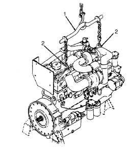
REMOVAL:
The engine lifting equipment must be designed
to safely lift the engine.
1.
Position a hoist with minimum rating of 3500 lb (1590
kg) with engine lifting fixture (1) attached over engine
assembly.
2.
Attach fixture (1) hooks to engine lifting brackets (2).
3.
Take up slack in hoist chain without applying a lifting
force to engine assembly.
3-48