6-8
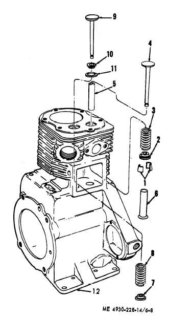
b . D i s a s s e m b l y . R e f e r t o f i g u r e 6 - 8 a nd
disassemble the valves, valve seats, guides, and
springs.
1 Lock (4)
2 Spring seat
3 Spring
4 Intake valve
5 Guide
6 Tappet (2)
7 Rotator
8 Spring
9 Exhaust valve
10 Cup (2)
11 Insert
12 Crankcase
Figure 6-8. Valves, exploded view.
c. Cleaning, Inspection, and Repair.
(1) Clean the valves with a wire brush to
remove all carbon deposits. Clean valve seats,
ports, and guides in cylinder block; clean top of
cylinder block. Wash springs with cleaning solvent
and dry thoroughly.
( 2 ) I n s p e c t v a l v e s f o r b u r n e d , p i t t e d , or
cracked faces: replace a burned, cracked, or deeply
pitted valve.
(3) Inspect valves springs for cracks or pitting.
Replace cracked or pitted springs.
(4) Inspect valve seat insert for looseness and
pitting. Replace a defective valve seat insert in the
following manner:
(a) Use a puller to remove the insert from
the exhaust valve opening.
( b ) C l e a n a l l c a r b o n o u t o f t h e i n s e rt
counterbore in the cylinder block and clean the
valve stem guide bore.
(c) Finish the counter bore in the cylinder
block to provide the correct bore-to-insert in-
terference. Chill the insert with dry ice and, using a
pilot driver, tap the insert into place with light
blows. Peen the insert to anchor in place.
(d) Reface the insert, if necessary, to make
its seat concentric with the valve. Check con-
centricity with a dial indicator.
(c) Lap valve in seat to form a gas-tight seat.
d. Regrinding Valves.
(1) Using a valve seat grinding tool, grind the
seats at a 45° angle and then grind the valve faces at
a 45° angle with a valve refacer grinder.
(2) Valves must be lapped with a suitable
lapping compound or they will leak within the first
few hours of operation because of improper seating.
(3) Clean valve seat and faces with cleaning
solvent and dry thoroughly.
(4) After lapping the valves, remove them
from the block and wash the valves and block with
cleaning solvent.
e . R e a s s e m b l y . R e f e r t o f i g u r e
6 - 8 a nd
reassemble valves.
f. Installation.
(1) Install valve inspection cover (para 6-8).
(2) Install cylinder head (para 6-7).
(3) Install carburetor (para 4-25).
(4) Install engine (para 6-5).
6-10. Engine Base and Oil Pump
a. Removal.
(1) Remove the engine (para 6-5).
(2) Refer to figure 6-9 and remove the engine
base and oil pump.
b . D i s a s s e m b l y . R e f e r t o f i g u r e 6 - 1 0 a nd
disassemble the engine base and oil pump.
c. Cleaning, Inspection, and Repair.
(1) Clean all parts with cleaning solvent and
dry thoroughly.