
TM 5-4320-218-15
Section XVIII. PUMP DISCHARGE MANIFOLD
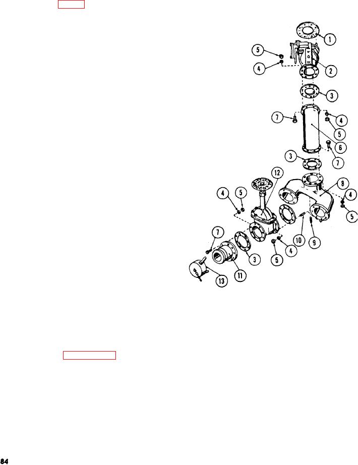
The purpose of the pump discharge mani-
fold (8) is to provide a multiple connection for
discharge hoses. Two 4-inch gate valves (12)
are mounted on the manifold. Each gate valve
is equipped with a flange adapter (11) and
dust cap (13).
135. Pump Discharge Manifold
Maintenance and Repair
a. Removal and disassembly.
(1) Remove the dust caps (13).
(2) Remove the nuts (5) and lockwashers
(4) and cap screws (7) securing the
adapters to the gate valves (12), Re-
move the adapters and gaskets (3 and
11).
(3) Remove the nuts (5) and lockwashers
(4) securing the gate valves (12) to
the discharge manifold (8). Remove
the gate valves and gaskets.
(4) Remove the nuts (5) and lockwashers
(4) and remove the discharge mani-
fold (8) from discharge elbow (6).
b. Cleaning, inspection, and repair.
(1) Clean all parts with an approved
cleaning solvent and dry thoroughly.
(2) Discard all gaskets removed and use
new gaskets for reassembly,
(3) Inspect all hardware for stripped
threads and wear. Replace any part
necessary,
(4) Inspect the manifold for cracks and
holes. Inspect the manifold flanges
for warpage and cracks, Replace a de-
1
Gasket and valve seat
fective manifold.
2
Valve assembly check
(5) Refer to paragraph 129 for mainte-
3
Gasket
4
nance and repair of the gate valves.
Lockwasher
5
Hex nut
(6) Inspect the dust caps for broken
6
Discharge elbow
chains, worn cam arms, and cam arm
7
Cap screw
pins. Replace worn arms and pins.
8
Discharge manifold
9
Pipe plug
(7) Inspect the extension pipes for cracks
stud
10
and damaged threads. Replace a dam-
11
Flange adapter
aged pipe.
12
Gate valve assembly
13
Dust cap
c. Reassembly and installation. Reverse the
procedure outlined in a above.
Figure 38. Pump discharge manifold, exploded view.