
TM 5-3825-270-10
0078
UNWIND HOSE REEL - Continued
4
5
6
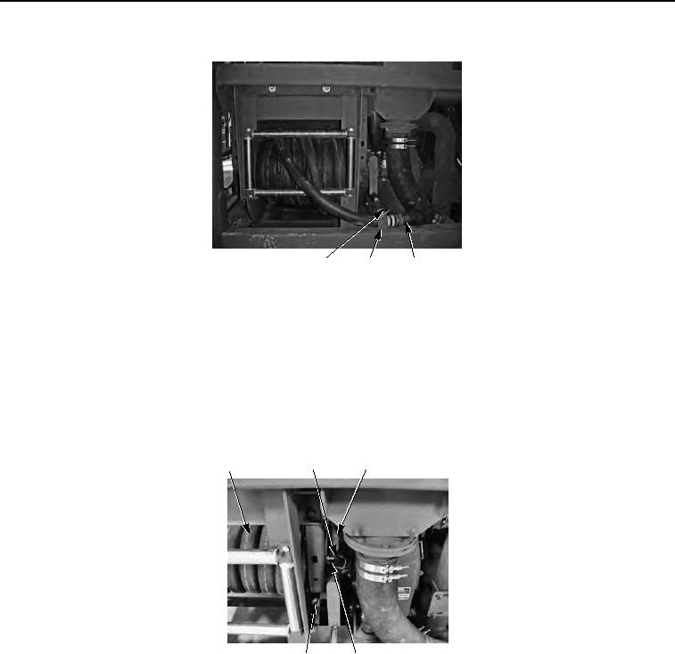
Figure 4. Unwind Hose Reel.
4.
With the aid of an assistant, pull hose (Figure 4, Item 6) to unwind.
END OF TASK
RETRACT HOSE REEL
1.
Remove retaining pin (Figure 5, Item 7) from crank handle (Figure 5, Item 8) and crank handle from stowage
brackets (Figure 5, Item 9).
8
6
7
10
9
Figure 5. Retract Hose Reel.
2.
Install crank handle (Figure 5, Item 8) on slotted shaft (Figure 5, Item 10).
3.
Reel hose (Figure 5, Item 6) in by turning crank handle (Figure 5, Item 8) clockwise.
4.
Remove crank handle (Figure 5, Item 8) from slotted shaft (Figure 5, Item 10) and return to stowage bracket
(Figure 5, Item 9). Secure with retaining pin (Figure 5, Item 7).
5.
Place hose (Figure 6, Item 6) in hose hook (Figure 6, Item 5) and secure with retaining pin (Figure 6, Item 4).