
TM 5-3820-276-10-2
0204
1
2
WWDS00355
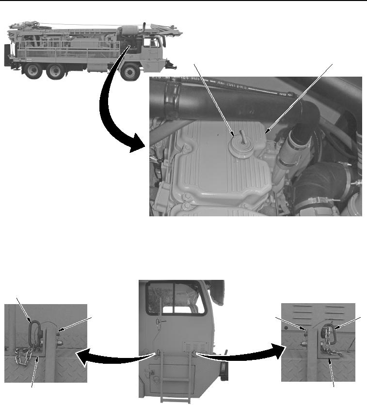
Figure 5.
Oil Fill Cap Installation.
18.
Remove two safety pins (Figure 6, Item 3) from pins (Figure 6, Item 1).
1
1
3
3
2
2
WWDS00656
Figure 6.
Ladder Pin Removal.
19.
Remove two pins (Figure 6, Item 1) from brackets (Figure 6, Item 2).
02/13/2013root(gen.maintwp)wpno(M00002)