
TM 5-3820-276-10-2
0198
Table 1.
PMCS - WWDR - Before Road and Towing Operation - Continued.
ITEM TO BE
EQUIPMENT
ITEM
CHECKED OR
NOT READY/
NO.
INTERVAL
SERVICED
PROCEDURE
AVAILABLE IF:
1
2
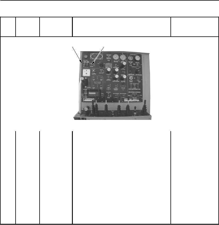
WWDS01006
Figure 25. Console Power Switch.
8. Check entire drill operator control panel (Figure 25,
Item 1) to ensure all gauges illuminate.
9. Check entire drill operator control panel (Figure 25,
Item 1) for damaged switches and broken glass.
10. Set CONSOLE POWER switch (Figure 25, Item 2)
to OFF.
11. Install console panel cover (Volume 1, WP 0029).
12. Place WWDR in road mode (Volume 1, WP 0017).
13. Shut down WWDR (Volume 1, WP 0012).
14. Install left-side ladder (Volume 1, WP 0029).
Any gauge does not
illuminate, switches or
levers damaged, or
gauges have broken
glass. Notify
maintenance.
02/13/2013root(pmcswp)wpno(I10001)