
TM 5-3820-276-10-1
0006
Table 2.
Operator Instrument Panel - WWDR and WWSV - Continued.
Key
Control/Indicator
Function
6.
Oil Pressure Gauge
Displays engine oil pressure in psi.
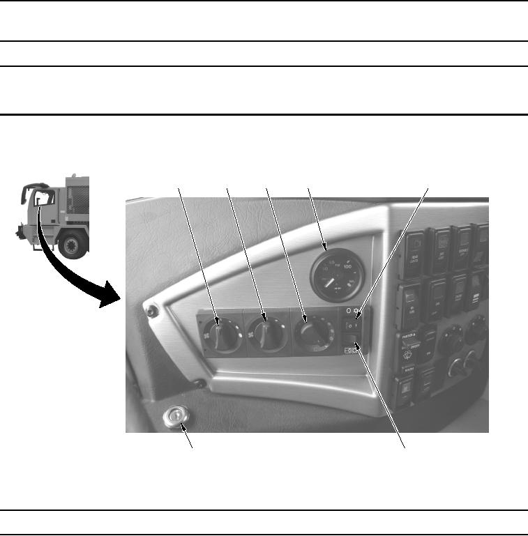
Table 3.
Engine Ignition Switch, Cab Heater/Air Conditioning, and Air Pressure Gauge - WWDR and
WWSV.
1
2
3
4
5
7
6
WWDS00057
Figure 3.
Engine Ignition Switch, Cab Heater/Air Conditioning, and Air Pressure Gauge - WWDR and
WWSV.
Key
Control/Indicator
Function
1.
Fan Switch
Used to control speed of heater/air conditioning fan.
2.
Heater Control
Used to direct air flow to dash panel, floor, or defroster.
Switch
3.
Heater Control
Used to control temperature of air output.