
TM 5-3820-276-10-1
0003
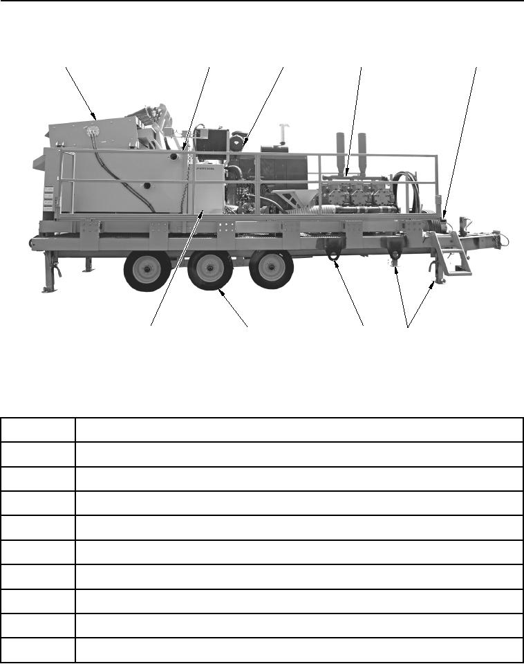
MCS LOCATION AND DESCRIPTION OF MAJOR COMPONENTS - RIGHT-SIDE VIEW
1
2
3
4
5
9
8
7
6
WWDS00011
Figure 8.
MCS Right-Side View.
Table 8.
MCS Right-Side Item Location.
Item
Nomenclature
1
Shaker System With Desander Cones
2
Catwalk
3
Engine
4
Mud Pump
5
Auxiliary Power Unit
6
Leveling Jacks
7
Tiedowns
8
Wheels and Tires
9
Fuel Tank 35 gal. (132 L) and Hydraulic Tank 65 gal. (246 L)
02/13/2013root(descwp)wpno(G00002)