TM 10-4930-236-13&P
REMOVAL
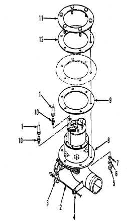
a.
Disconnect tubes (1) at jet
level sensor.
b.
Withdraw cable (2) from lever
(3) and bushing (4).
c.
Remove nuts (5), lockwashers
(6), flat washers (7), bottom loading
valve (8) and gasket (9).
d.
Disconnect tubes (1) and remove
connectors (10).
e
Reach through mounting hole and
lift retainer (11) up and away from gasket
(12). Remove gasket through hole.
DISASSEMBLY
a
Remove screws (13), plug (14) from
SECONDARY port and pilot assembly (153 from
PRIMARY port.
WARNING
Parts under spring tension can cause serious injury. Take
extreme care when releasing parts under spring tension.
b.
Remove screws (16) and lift off cap (17).
c.
Remove garter spring (18), seal (19) and spring (20).
d.
Remove retaining ring (21) and seal assembly (22) from cap (17).
e.
Remove screen (23), spring (24), pin (25) and lever (26).
f.
Unscrew gland (27) and remove gland and shah (28).
g.
Remove O-ring packing (29) and seal/retainer assembly (30) from gland (27).
h.
Pins (31) may remain in shaft (28) unless they must be replaced due to damage.
i.
Remove shaft (32) from valve body (33) with parts attached to shaft.
j.
Remove hair pin (34), pin (35) and cam (36).
k.
Depress shaft (32) into piston (44) then remove cotter pin (37), washer (38), limitpin (39), links (40), spring (41)
and orifice (42).
5-20