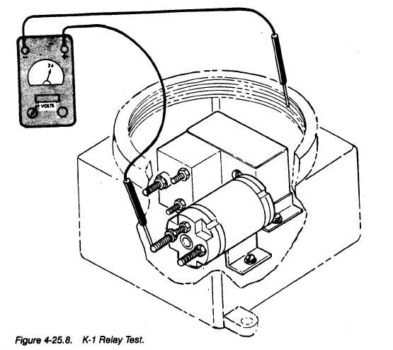
Figure 4-25.8.
TM 10-4930-204-13
d. RF Filter Test Procedures
(1) Step 1.
(a) Disconnect Power Cable (J2),
(b) Unscrew and remove Junction Box Cover with O-ring.
(2) Step 2. (See figure 4-25.7)
(a) Tag and remove wires from terminals 4,5, and 6.
(b) Remove four screws from top cover of RF Filter exposing terminals 4,5, and 6.
(c)Tag and remove motor wires from terminals 1,2, and 3.
NOTE
Continuity indicates shorted RF Filter and a need for
replacement.
(3) Step 3. Test RF Filter wires for continuity across terminals 4 and 6;
and across terminals
5 and 6.
-.
-.
4-48.12
Change 6