4.4.21 Engine Block Maintenance, Unit 609-A.
(Continued)
Irregularities in cylinder bore may result in
h.
Check cylinder bore out-of-round and taper.
0.003 inches (0.076 mm).
Taper must not be
in each cylinder bore.
galling and seizing of
Out-of-round must not
more than 0.002 inches
p i s t o n s .
exceed
(0.051 mm)
i .
Using accurate straight edge and a feeler gage, check top of engine block (1)
f o r f l a t n e s s.
Top of surface may not vary-more than 0.005 inches (0.127 mm)
on width or length.
Out-of-flatness should vary gradually and uniformly from
end to end and side to side.
j .
Replace any damaged, loose, or broken dowel pin (18).
k.
Refer to paragraph 2.11.2 and replace any damaged, loose, or broken studs
(17).
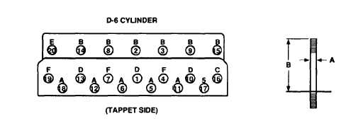
Figure 4-39.
Engine
Install end oil passage studs so
center line of rocker arm shaft.
Block Stud Location, Model 609-A.
that oil holes are within a 40° angle with
1.
If necessary, add adhesive in hole and install new stud(s) (17) in engine
block (1) to dimensions indicated in Table 4-17.
(Refer to Figure 4-39.)
Table 4-17.
Stud Dimensions.
6 Cylinder
Stud
A-Diameter
B-Height
A
0.562 inches (14.275 mm)
4.620 inches (117.348 mm)
B
0.625 inches (15.875 mm)
4.680 inches (118.872 mm)
C - Oil Supply
0.625 inches (15.875 mm)
6.620 inches (168.148 mm)
D - Cover
0.625 inches (15.875 mm)
7.430 inches (188.722 mm)
E - Lift
0.625 inches (15.875 mm)
5.810 inches (147.574 mm)
F
0.625 inches (15.875 mm)
6.620 inches (168.148 mm)
m.
Check main bearing bores of engine block (Figure 4-38, 1) as follows:
4-78
TM 10-4320-344-24