TM 10-4320-344-24
3.8.17 Rocker Arm Assembly Maintenance. Model 609-A. (Continued)
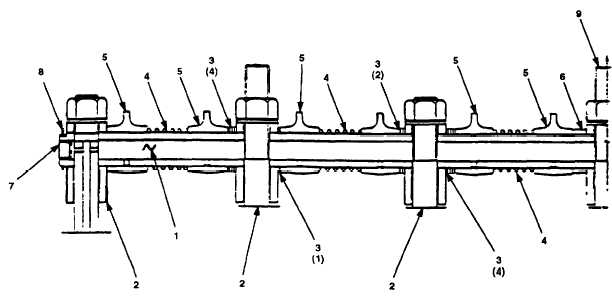
Figure 3-37.
Rocker Arm Assembly Installation, Model 609-A.
f .
Tie a wire between number 1 rocker arm (Figure 3-35, 1) and number 12 rocker
arm (2).
Make sure wire is tied tightly enough to maintain tension on spacing
springs while rocker arm assembly (5) is being installed.
3.8.17.5 Installation.
B e f o r e i n s t a l l i ng
arms are properly
rocker arm assembly on cylinder head, check that rocker
installed and move freely on rocker arm shaft.
a.
Install rocker arm assembly (5) over center head studs on cylinder head (6)
and seat rocker arm assembly (5) firmly on cylinder head (6).
Ensure rocker
arm adjusting screws (Figure 3-36,
10) are positioned over push-rods in
cylinder head (Figure 3-35, 6).
b .
Install seven flat washers (4) and nuts (3) on center head studs of cylinder
head (6).
Hand tighten nuts (3).
c .
Remove wire from rocker arm assembly (5).
When tightening mounting nuts on rocker arm
work outward.
Tighten each nut a few turns
is placed on all valve springs.
assembly, start at center nut and
at a time so that equal tension
d.
Following sequence shown in Figure 3-38, torque nuts to 75 ft-lbs (102 N•m),
then to 125 ft-lbs (170 N•m), and finally to 147 ft-lbs (199 N•m).
e .
Refer to paragraph 2.21.49 and perform cold valve adjustment.
3-86
NOTE
NOTE


