TM 10-4320-321-13&P
FORM 5S2583
MODELS 2P121 THRU 2P128 & WP373 THRU 2P380
01615
Maintenance (Continued)
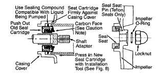
Figure 7. Mechanical Seal Replacement (Teflon Seal
Shown)
3.
Unscrew impeller (Ref. No. 14) from the shaft
adapter. Remove the impeller O-ring (Ref. No. 15)
and clear all sediment from impeller. Inspect the
impeller O-ring, replace if deeply scarred or worn.
NOTE: DO NOT remove or adjust shaft adapter (Ref. No. 3).
4.
Pry seal seat (Ref. No. 12) from recess of impeller.
Use caution so as not to damage or remove seal seat
pin (Ref. No. 13) on Teflon seal equipped units.
5.
Remove the adapter and casing cover (Ref. Nos. 5 &
8) by unthreading four fasteners (Ref. Nos. 7 & 22; two
of each).
6.
Press seal cartridge (Ref. No. 11) from the rear of the
casing cover.
7.
Clean casing cover and impeller seal recesses and
shaft adapter. Make certain all surfaces are perfectly
clean before installing new seal parts.
CAUTION: Handle seal parts with extreme caution and keep them
clean. Do not touch seal faces (either ceramic or carbon) with your
hands. Do not apply lubricants on seal faces. This could cause a leak
or premature seal failure.
8.
Apply a light coat of sealing compound to new seal
cartridge (See Figure 7) and press it into the casing
cover recess using the proper size tube or installation
tool (See Figure 8). DO NOT press on carbon face or
top of metal cup of the seal cartridge. Install using
flange only.
9.
Slide the assembled adapter and casing cover (Ref.
Nos. 5 & 8) onto motor mounting face. Fasten with
four fasteners (Ref. Nos. 7 & 22; two of each), making
sure that the mounting foot (Ref. No. 23) is in place.
10. Press new seal seat (Ref. No. 12) squarely into the
impeller recess. Align slot in the seal seat with seal
seat pin (Ref. No. 13) on Teflon equipped units. Avoid
scratching the ceramic surface.
NOTE: Use a soft, clean piece of cloth on seal seat face when
installing to prevent marring.
11. Screw the impeller back in place, tightening until it is
firmly seated.
12. Install the impeller 0-ring (Ref. No. 15) and install and
tighten impeller locknut (Ref. No. 16).
13. Reinstall O-ring seal (Ref. No. 10) on casing cover
rabbet. Remount casing (Ref. No. 17) with six
fasteners (Ref. No. 9).
14. If 3/16" hex key (Allen wrench) was inserted into the
shaft adapter clamp screw to prevent shaft rotation,
remove it. Pump may now be returned to service.
NOTE: Always flush pump thoroughly before use so as not to
contaminate liquid being pumped.
IMPELLER CLEARANCE ADJUSTMENT
When installing replacement motor, shaft adapter
(Ref. No. 3), adapter (Ref. No. 5), casing cover
(Ref. No. 8), impeller (Ref. No. 14) or casing (Ref.
No. 17), it may be necessary to adjust the
clearance between the impeller and casing faces.
NOTE: A proper running clearance is less than 0.021".
CAUTION: If the impeller (Ref. No. 14) is replaced, the seal
assembly should also be replaced as the seal is usually
damaged in disassembly. Also replace Teflon washer (Ref.
No. 15).
1.
After the replacement components have been
installed, reassemble the pump as described
under "Mechanical Seal Replacement". DO
NOT remount pump casing (Ref. No. 17) at this
time.
2.
Loosen lock screws (Ref. No. 1) in shaft
adapter clamp (Ref. No. 2) as the impeller will
move in and out freely. Leave loose but do not
remove the assembly from the motor shaft
(screws
are
accessible
through
adapter
openings).
3.
Stand the pump up on motor end if possible
and place a 0.020" feeler gauge in the face of
the impeller (if feeler gauge is not available,
use five to six thicknesses of newspaper. Make
sure impeller and casing are absolutely dry and
clean). With pump still on end, remount the
casing (Ref. No. 17) tightening fasteners (Ref.
No. 9) evenly.
4.
Make certain the full width of shaft adapter
clamp (Ref. No. 2) is in place on shaft adapter
and the split in the shaft adapter (Ref. No. 3) is
aligned with the part between the clamp halves
and retighten lock screws (Ref. No. 1).
5.
Unthread fasteners (Ref. No. 9) and remove
casing (Ref. No. 17). Remove feeler gauge (or
newspaper pieces). Then mount casing making
certain all fasteners are tight.
NOTE: Make certain that O-ring seal (Ref. No. 10) is in place.
6.
Check shaft to make sure it turns freely (turn
shaft with shaft adapter clamp). This procedure
should insure the proper running clearance and
will deliver maximum performance from the
pump.
NOTE: If shaft will not turn, remove casing (Ref. No. 17) and
repeat above procedure beginning with step 2.
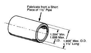
Figure 8 - Seal Installation Tool
-7-