TM 10-4320-318-14
5-5. MAINTENANCE OF FUEL INJECTION PUMP - (Cont)
(e)
Install shims (3, Figure 5-3) onto flange of crankcase (8). Then insert injection pump (2) carefully
without moving governor sleeve (5) out of its proper position.
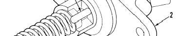
Figure 5-4. Injection Pump Governor Sleeve Pin
NOTE
If fuel injection pump cannot be inserted flush, the small pin (Figure 5-4)
at the governor sleeve has not entered the slot in the governor lever.
(9 Apply hand pressure and install fuel injection pump (2, Figure 5-3).
CAUTION
Installing nuts for securing injection pump with small pin (Figure 5-4) at
governor sleeve not in the slot of governor lever may cause damage to
injection pump, governor lever, and/or entire engine if engine starts with
a binding governor.
(5) Install nuts (1, Figure 5-3) and secure injection pump (2) to crankcase (8).
NOTE
Reaching each position, a noise caused by governor lever and the
eccentric pin will be heard.
(6) Check for governor binding by moving speed control lever (1, Figure 5-2) from the START to STOP
positions several times. Observe click at each position.
5 -7