TM 5-3820-276-10-1
OPERATOR MAINTENANCE
DESCRIPTION AND USE OF CONTROLS AND INDICATORS - WELDER/GENERATOR
INTRODUCTION
This section provides the features and functions of the welder/generator control panel.
NOTE
Before attempting to operate the welder/generator be familiar with the location and function
of all controls and indicators.
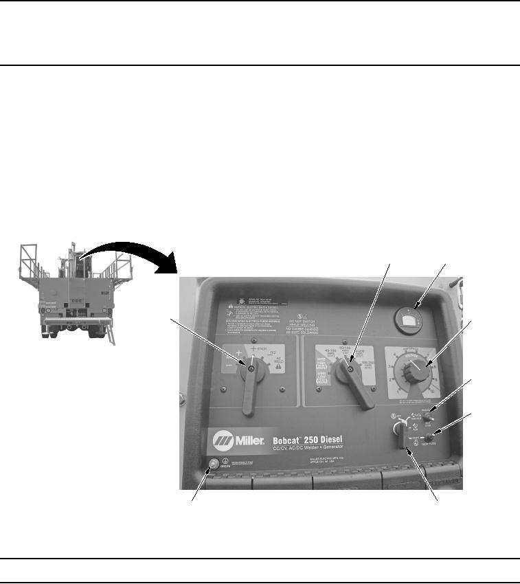
The illustrations that follow provide the description and use of the welder/generator control panel.
Table 1.
Upper Control Panel.
2
3
4
1
5
6
8
7
WWDS00216
Figure 1.
Upper Control Panel.
Key
Control/Indicator
Function
1.
Weld Process
Used to select type of weld output. WIRE: Use positive (+) position for Direct
Selector Switch
Current Electrode Positive (DCEP) and negative (-) position for Direct
Current Electrode Negative (DCEN). STICK and TIG: Use positive (+)
position for DCEP and negative (-) position for DCEN. Use AC WELD
position for alternating current.