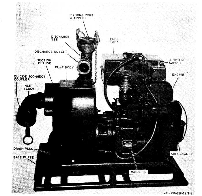
c. Pump. The pump (fig. 1-4) is self-priming
engine are mounted on a base plate to facilitate
unit, with the impeller screwed directly on the
removal for use in auxiliary pumping operations.
extension of the engine crankshaft. The pump and
Figure 1-4. Pump and engine
d. Engine. The engine (fig. 1-2) is a one-cylinder,
4-cycle, air-cooled, hand-cranked, gasoline engine.
It is provided with a radio-interference suppressed
magneto and a governor that controls engine speeds
to suit pump loads as the throttle setting is varied.
e. Filter/Separator. The filter / separator (fig.
1-3) is a vertical, 50-gpm unit designed for a
assembly, three-quarter view.
maximum operating pressure of 75 psi (pounds per
square inch). Both solids and water (free from
entrained water) are removed from the fuel through
coalescing and filtering medium of the elements
inside the filter separator. The filter / separator has
four canisters and filter elements, one differential
pressure indicator, one water sight gage, and one
1-7