
TM 5-4320-275-13 & P
FRAME ASSEMBLY (CONT)
LOCATION/ITEM
ACTION
REMARKS
ASSEMBLY
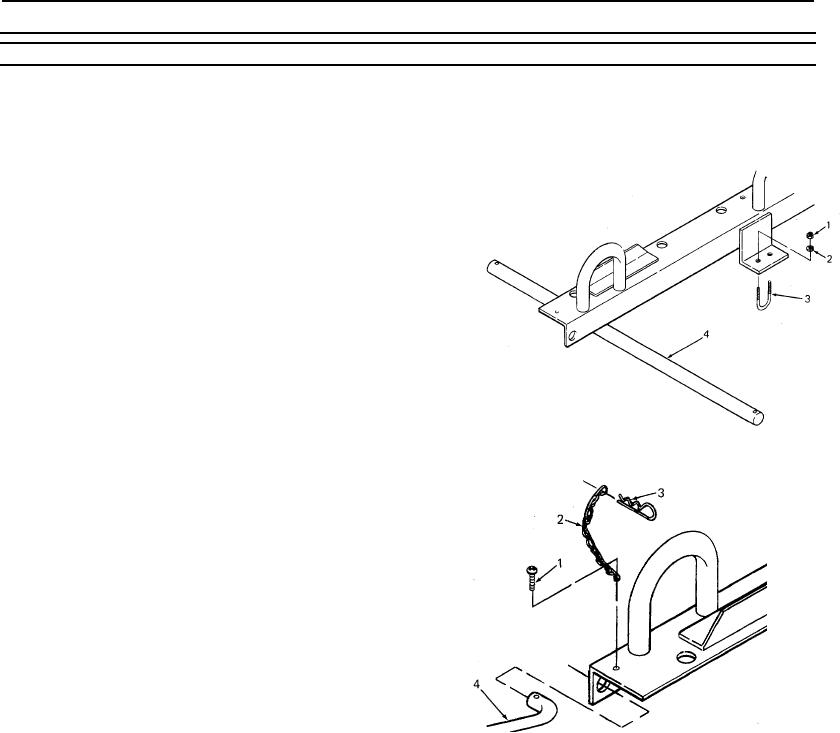
15. Axle
Set axle (4) against frame and hold in place
with U-bolts (3). Install lockwashers (2) and
nuts (1). Use Loctite on
threads.
16. Align axle
Slide axle (4) in U-
bolts (3) until
each end of the axle is equal
dis-
tance from the frame.
17. Nuts
Use 1/2 inch
wrench to tighten
nuts (1)
to 4 ft lb (5 Nm).
NOTE
Do not tighten U-bolts against axle.
18. Chains
Install hitch pin (3) on chain
(2).
19. Screws
Insert screw (1) through the
last link in chain (2). Use
cross point screwdriver to
install screw (1) into frame.
Use Loctite on threads.
20. Draw bar
Insert draw bar (4) ends
into frame. Install hitch
pins (3) into each end of
draw bar.
4-45