
TM 5-4320-275-13 & P
Section III. PRINCIPLES OF OPERATION
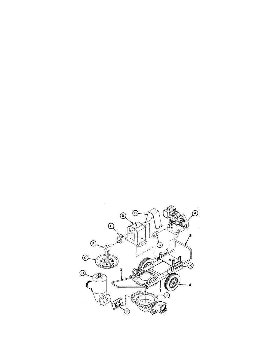
1-12. DIAPHRAGM PUMP
Consists of a gasoline engine and a wheel-mounted diaphragm pump. Power from the engine is transferred to the pump
through a floating coupling, gear reducer, crank, and connecting rod.
(A)
ENGINE. Secured by engine mount to base assembly.
(B)
COUPLING GUARD. Serves as a safety device if. coupling should shear.
(C)
FLOATING COUPLING. Connects engine drive shaft to gear reducer input shaft.
(D)
GEAR REDUCER. Serves as a speed reducer to transfer engine power to the pump.
(E)
CRANK. Fitted to the gear reducer output shaft to change the circular motion of the shaft to lift-and-force
motion of the connecting rod.
(F)
CONNECTING ROD. Serves as the link between the crank and the pump diaphragm.
(G)
PUMP DIAPHRAGM. Changes the lift-and-force motion to suction and discharge pressure to move the
water through the pump.
(H)
ACCUMULATOR. Serves as a reservoir to provide a constant flow of inlet water and to eliminate priming.
(I)
BYPASS VALVE ASSEMBLY. The suction side bypass valve assembly starts to open when the pump
diaphragm begins the lift position and the discharge side bypass valve assembly starts to close. When the
pump diaphragm starts moving to the force position, the suction side bypass assembly starts to close and the
discharge side bypass valve assembly starts to open.
(J)
BOWL. Serves as the pump base to mount. the diaphragm and bypass valve assemblies. Provides
directional control of pumped water.
(K)
FRAME ASSEMBLY WITH DRAW BAR, ENGINE GUARD, AND WHEELS. Serves as a mobile support for
all major assemblies.
1.
Frame Assembly
2.
Draw Bar
3.
Engine Guard
4.
Wheels
1-5/(1-6 blank)
