TM 5-4320-215-12
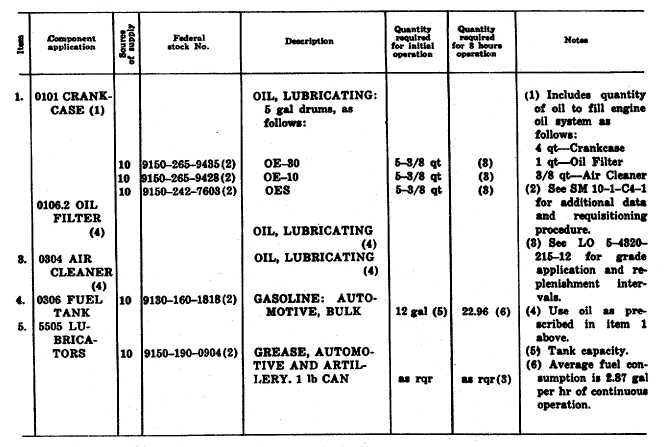
Table 1. Maintenance and Operating Supplies
fuels required for the initial operation of the pumping
unit.
g. Dimensions and Weight.
Length .............................100 1/8 in.
Width...............................55 1/2 in.
Height..............................69 1/2 in.
Weight.............................1,06 lb
h. Capacities.
Fuel tank..........................12 gal (gallons)
Crankcase........................4 qt (quarts)
Oil filter............................1 qt
Air cleaner .......................8/8 qt
i. Tires.
Size .................................7.00-16
Pressure ...........................46
psi
(pounds
per
square inch)
j. Wiring Diagram. Refer to figure 8 for the
practical wiring diagram for the electrical system.
6