Home
Download PDF
Order CD-ROM
Order in Print
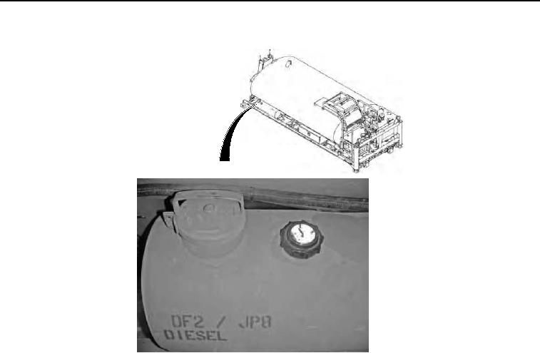
Figure 7. Stencils.
Figure 9. Stencils.
Technical Manual For Engineer Mission Module - Water Distributor
Page Navigation
359
360
361
362
363
364
365
366
367
368
369
TM
5-3825-270-10
0084
STENCILS
- Continued
Figure
8. Stencils.
6.
"V1,
V2,
V3,
V4,
V5,
V6,
V7,
and
V8"
are
stenciled
at
each
corresponding
valve.
0084-6