• Home
  • Download PDF
  • Order CD-ROM
  • Order in Print
Figure 10. Water Pump Connections.
Figure 12. Water Drain Valves (Left Side and Rear Shown in Closed Position).

Technical Manual For Water Well Drilling System (Wwds) - 2 Page Navigation
  677    678    679    680    681  682  683    684    685    686    687  
img
.
TM 5-3820-276-10-2
0225
WINTERIZE WATER WELL SUPPORT VEHICLE (WWSV) - Continued
10.
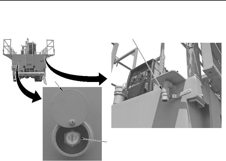
Open water tank vent valve (Figure 11, Item 1).
1
3
2
WWDS00931
Figure 11. Water Tank Vent Valve (Shown in Closed Position).
NOTE
Water drain valves are located on both sides and rear of WWSV.
11.
Make sure both water drain valves (Figure 12, Item 1) located on each side of WWSV are open half way to
drain water.
0225-12
02/13/2013root(maintwp)wpno(M20008)


Privacy Statement
Press Release
Contact

© Copyright Integrated Publishing, Inc.. All Rights Reserved.