
TM 10-4630-207-13&P
OPERATOR, UNIT AND DIRECT SUPPORT MAINTENANCE
WASTEWATER EVACUATION TANK TRAILER
THEORY OF OPERATION
THEORY OF OPERATION
General. The WWET/T is a trailer-mounted wastewater evacuation system for operation in temperatures
above 32 0F. An on-board vacuum/pressure system is used to load the 1,000 Gallon capacity wastewater
tank at the evacuation point and discharge it at the disposal point. A water-cooled, four-cycle, in-line
overhead valve type, diesel engine provides the power to operate a vane-type vacuum pump. The pump
creates a vacuum in the tank during loading, and pressurizes the tank during unloading. The intake and
drain valves located at the back of the trailer are operated through a manual hydraulic hand pump. A float
ball type shutoff located at the top of the tank blocks the airflow when the tank is full. A moisture trap, or
secondary shutoff, is located externally, in front of the tank. A float level indicator activated by a separate
float ball indicates the fluid level in the tank. A 12-Volt battery provides starting power for the diesel engine.
The trailer is fully equipped with running, backup and license plate lights and connects to the prime mover
using an adjustable lunette. It can be towed over the road as well as rough terrain. See Figures 1 and 2.
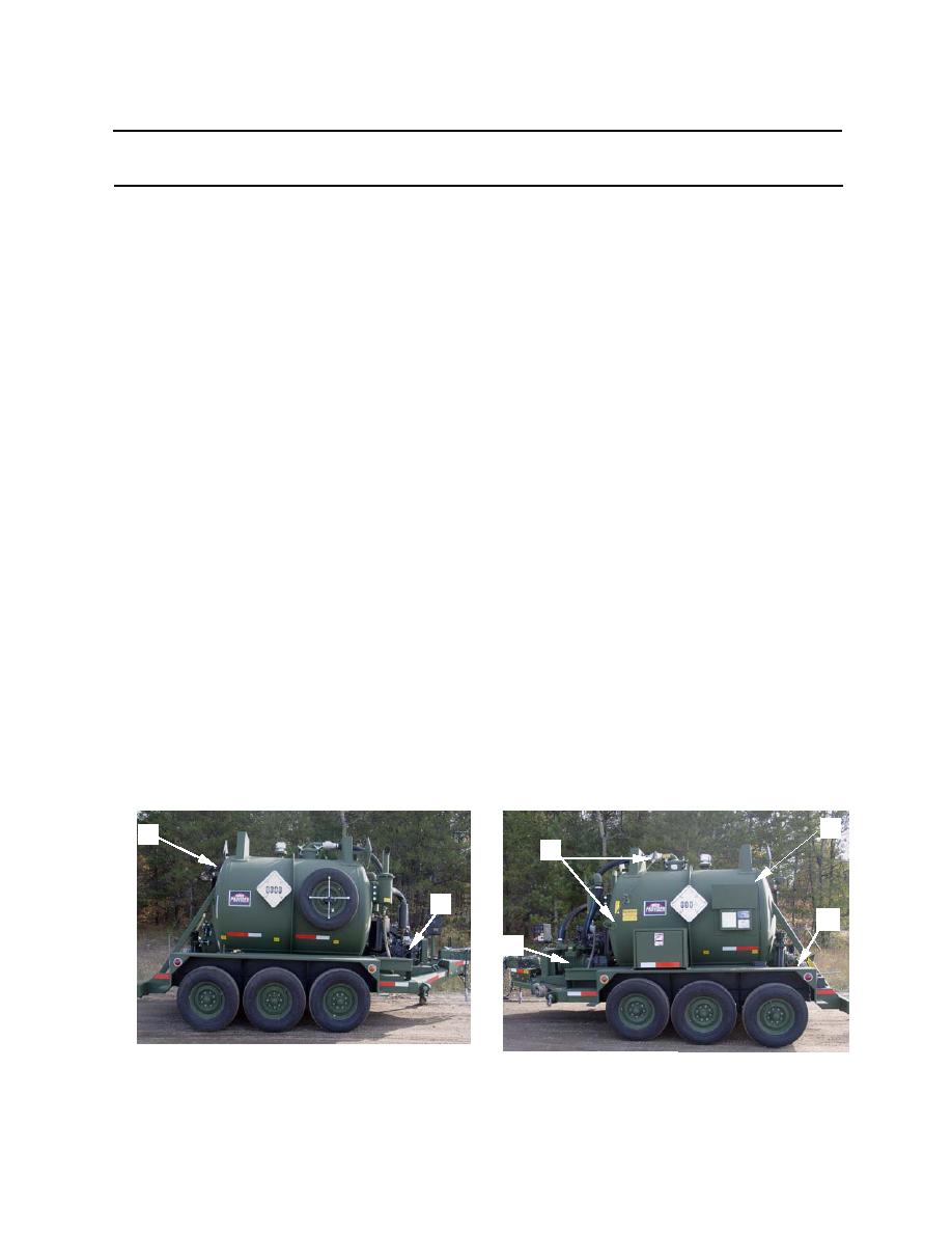
Operational Concept. (Loading) The WWET/T (1) is positioned within 20 to 30-feet of the facility to be
serviced. Two intake hoses (2-inch x 20-foot) (2) and a chopper tube/wand (3) are then assembled in
series. The assembled hoses are then attached to the intake valve (4). With the chopper tube/wand
immersed in the liquid to be evacuated, the diesel engine (5) is started and the vacuum pump (6) set to the
VACUUM function. The isolation valve (7) and intake valve (4) are opened. When a specified vacuum
(approximately 15-inch/vac) is reached as indicated on the pressure gage (8), the ball valve (9) located on
the chopper tube/wand is opened and the tank will fill. The float level indicator (10) indicates the level of
the accumulating liquid in the tank. When the tank is full a primary shutoff mechanism located inside the
tank will terminate the loading function. The intake valve (4) and isolation valve (7) is then closed. The
intake hoses and chopper tube/wand are then removed and the trailer can be moved to the disposal point.
(Disposal) With the WWET/T positioned within 10 to 15-feet of the disposal point, two 4-inch drain hoses,
assembled in series (11), are attached to the drain valve (12) and the disposal facility. The drain valve (12)
and the isolation valve (7) are then opened to let the liquid drain from the tank. To drain the tank under
pressure, the diesel engine (5) is started and the vacuum pump (6) set to the PRESSURE function. As
pressure builds inside the tank, the contents are expelled. When the tank is empty as shown on the float
level indicator (10) the drain valve (12) is closed and the assembled 4-inch x 10-foot hoses (11)
disconnected. A 20-inch hatch (13) located at the rear of the tank can be opened to remove solids that will
not evacuate during normal unloading.
1
1
7
5
4
6
Figure 1. Location Of Major Components
0003 00-1
