TM 10-4320-344-24
4.4.2 Cylinder Head Assembly, Intake Valve, and Exhaust Valve Repair, Models 609-C and US636HCCD-1.
(Continued)
Table 4-4.
Intake Valve Fits and Tolerances, Models 609-C
and US636HCCD-1.
(continued)
Dimension
Limit
Seat Bore Diameter In
C y l i n d e r H e a d
Valve Recessed Below
Cylinder Head Deck
Minimum
Maximum
0.0016 inches (0.04 mm)
0.0028 inches (0.07 mm)
0.0059 inches (0.15 mm)
1.7913 inches (45.50 mm)
1.7923 inches (45.525 mm)
1.7969 inches (45.64 mm)
1.7976 inches (45.66 mm)
45°
(30°)
0.0197 inches (0.50 mm)
0.0393 inches (1.00 mm)
{0.0512 inches (1.30 mm)}
{0.0709 inches (1.80 mm)}
0.20 inches (5.08 mm)
0.2598 inches (6.6 mm)
with intermediate ring
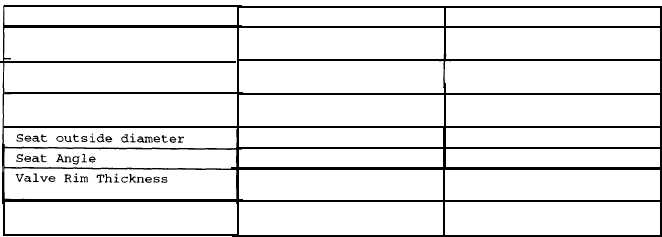
Table 4-5.
Exhaust Valve Fits and Tolerances, Models 609-C and US636HCCD-1.
Dimension
Stem Diameter
Head Diameter
Standard
Valve Stem Clearance - Wear
Limit
Seat Bore Diameter In
Cylinder Head
Seat outside diameter
Seat Angle
Valve Rim Thickness
Valve Recessed Below
Cylinder Head Deck
d .
Replace any valves (6 and
Minimum
Maximum
0.3118 inches (7.92 mm)
0.3126 inches (7.94 mm)
1.4528 inches (36.9 mm)
1.4606 inches (37.1 mm)
0.059 inches (1.50 mm)
0.079 inches (2.00 mm)
0.0024 inches (0.06 mm)
0.0037 inches (0.095 mm)
0.0079 inches (0.2 mm)
1.5748 inches (40 mm)
1.5758 inches (40.025 mm)
1.5803 inches (40.14 mm)
1.5811 in. (40.16 mm)
45°
0.0276 inches (0.70 mm)
0.0591 inches (1.50 mm)
0.20 inches (5.08 mm)
0.2598 inches (6.6 mm)
with intermediate ring
7) which are damaged or out of tolerance.
e .
Inspect cylinder head (1) for damage and replace if damaged.
f .
Check that cylinder head seating surface (Figure 4-3, 1) is flat and square.
Seating surface can be ground.
g.
After reworking, measure clearance between cylinder head bottom and cylinder
head seating surface.
The measured value may not be lower than 0.2323 inches
(5.9 nun) with intermediate ring.
4-10
Valve stem Clearance -
Standard
Valve stem Clearance - Wear
Valve Seat Width
Valve Stem Clearance -