TM 10-4930-204-13
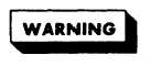
Legend for figure 5-18:
1.
2.
3.
4.
5.
6.
ket (11),
(14), and
Setscrew
7.
Pin
8.
Rod and handle
9.
Control rod packing nut
10.
Support
11.
Collar
(3) Remove nut (8), washer (9),
Key
Valve packing
Elbow
Globe (angle) valve
Nipple
sump ring (10), upper gas-
lower gasket (12), and disconnect valve assembly from tank.
(4) Remove inlet strainer screen (13), plunger stem bale
plunger stem (15).
NOTE
Cap (17) is spring loaded and should be held down
when loosening setscrew (16).
(5) Loosen setscrew (16) and remove cap (17), plunger
spring (18), seat retainer (19), plunger disk (20), and retainer nut
(21) from valve body (22).
(6) Remove dust cap (23), dust cap gasket (24), and outlet
strainer screen (25) from valve’ body.
Disconnect chain (26) from dust
cap and valve body as necessary.
b.
Cleaning and Inspection.
a flash point
Drycleaning solvent normally has
of either 100 or 138 degrees F, depending on the
type being used, but may flash at much lower tem-
peratures if contaminated with gasoline or jet
fuel.
Avoid repeated and prolonged skin contact.
Do not use near open flame or excessive heat.
(1) Clean parts with drycleaning solvent (item 1, App. F).
Immerse each part in solvent a-rid remove contaminants by brushing.
Allow parts to dry thoroughly.
(2) Straighten bent operating lever rod or lift rod. If
rod is not repairable, replace it with a serviceable one.
(3) Inspect remaining valve assembly parts for any damage
or defects.
Replace damaged or defective parts.
5-43