TM 10-4320-344-24
4.4.17 Camshaft Maintenance, Models 609-C and US636HCCD-1. (Continued)
d.
e .
f .
g .
h.
i .
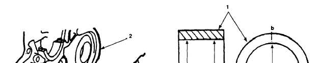
Inspect camshaft assembly (2) for scored or worn cams and bearing surfaces and
worn thrust surfaces.
Inspect camshaft gear (6) for burrs, chips, cracks, damaged or missing teeth,
or damage.
Measure diameter of camshaft bearing journal at drive end of camshaft assembly
(2). Record measurement.
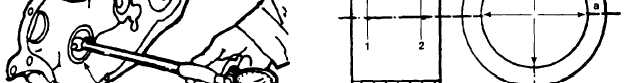
Figure 4-32. Camshaft Inspection, Models 609-C and US636HCCD-1.
Using micrometer, measure inside diameter of camshaft bearing sleeve (Figure
4-32, 1) in crankcase (2) at points "1" and "2" in planes "a" and "b" as shown
in Figure 4-32. Record measurement.
If camshaft bearing sleeve (1) measurement is not within 1.8890 - 1.8911
inches (47.980 - 48.034 mm) refer to paragraph 4.4.22 and replace camshaft
bearing sleeve (1).
Subtract measurement taken in step f from measurement taken in step g. If
resultant value is greater than or equal to 0.0394 inches (1.000 mm), replace
camshaft assembly (Figure 4-31, 2) and refer to paragraph 4.4.22 and replace
camshaft bearing-sleeve (Figure 4-32, 1).
4.4.17.3 Installation.
To avoid damage to equipment, ensure valve tappets are installed in their
original cylinders block holes.
a .
Lightly coat valve tappets (Figure 4-31, 1) with oil, remove tags, and insert
valve tappets (1) into-their respective holes in crankcase (3). Push valve
tappets (1) all the way in, so they will clear camshaft assembly (2).
b.
Install thrust washer (5) on camshaft assembly (2).
c .
Install pin (4) in camshaft assembly (2).
4-62