TM 10-4320-307-24
4-14
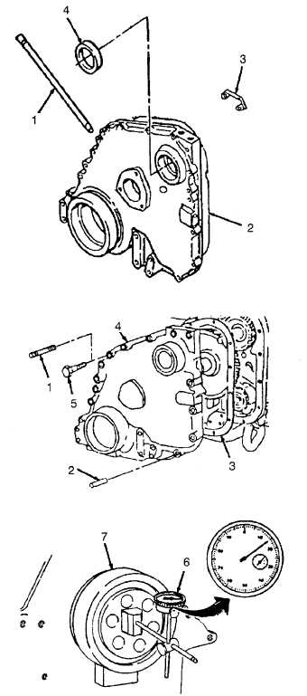
GEAR COVER ASSEMBLY REPAIR/REPLACE_(CONT).
ASSEMBLY:
1.
Install tube (1) to gear cover (2).
2.
Install pointer (3) to gear cover (2).
CAUTION
Make sure bushing and gear cover oil
holes are in alignment. A 0.156-inch
(3.96 mm) diameter rod must pass freely
through oil holes.
3.
Press accessory drive seal (4) into gear cover (2) using
arbor press and accessory drive bushing mandrel.
INSTALLATION:
1.
Install one 7/16-20 x 4-inch guide stud (1) in each side
of gear cover mounting flange.
2.
Install two dowel pins (2).
3.
Install gear cover gasket (3) over guide studs (1) and
dowel pins (2).
NOTE
Use a film of grease to hold the gasket in
place if necessary.
4.
Install gear cover (4) over guide studs (1) and dowel
pins (2).
5.
Install mounting capscrews (5) hand tight.
6.
Remove two guide studs (1) and replace with mounting
capscrews (5).
7.
Tighten capscrews (5) to 50 ft-lbs (70 N•m) torque.
8.
Cut ends of gasket (3) off even with oil pan mounting
flange.
9.
Mount dial indicator (6) on front face of crankshaft
(7). Put indicator plunger against oil seal bore, and
set dial indicator to 0 (zero).
10. Rotate crankshaft one complete revolution while
monitoring indicator. Total indicator reading must
not exceed 0.010 inch (0.025 mm).
4-101