CHAPTER 6
REPAIR INSTRUCTIONS
Section I. PUMP AND INTERMEDIATE COUPLING
6-1. General
engine crankshaft and coupling head to prevent
The pump is coupled to the engine by an in-
fluid from leaking around the rotating shaft.
termediate coupling. One side of the coupling bolts
to the engine; the pump housing bolts to the op-
posite side. The pump impeller is threaded and
screws directly to the engine crankshaft. Impeller- 6-2.
to-wear plate clearance is regulated by gaskets and
a.
NOTE
Evidence of leakage between the intermediate
coupling and engine will indicate a defective seal.
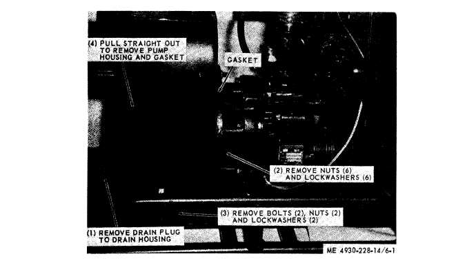
Pump and Intermediate Coupling
Disassembly. Refer to figure 6-1 and remove
shims. A seal assembly is installed between the
pump housing.
Figure 6-1. Pump housing removal.
6-1