6-4
TM 5-4930-227-14
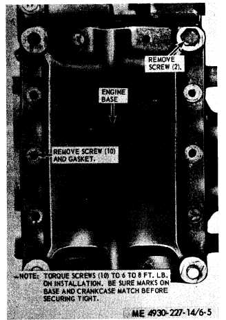
Figure 6-5. Engine base and oil pump, removal and
installation.
6-6. Piston and Connecting Rod
a. Removal.
(1) Remove the engine base (para 6-5).
(2) Remove the cylinder head (para 6-2).
(3) Refer to figure 6-7 and remove the pis-
ton and connecting rod.
b. Disassembly. Refer to figure 6-8 and disas-
semble the piston and connecting rod.
c. Cleaning, Inspection, and Repair.
(1) Clean all parts with an approved clean-
ing solvent and dry thoroughly.
(2) Inspect all parts for cracks, breaks, and
other damage. Replace a damaged or defective
part.
(3) Inspect the mounting hardware for dam-
aged or stripped threads. Replace a damaged or
defective part.
d. Reassembly.
semble the piston
Refer to figure 6-8 and reas-
and connecting rod.
6-7. Crankshaft
a. Removal.
(1) Remove the piston and connecting rod
(para 6-6).
(2) Refer to figure 6-9; remove the crank-
shaft.
b. Disassembly. Refer to figure 6-10 and dis-
assemble the crankshaft.
c. Cleaning, Inspection, and Repair.
(1) Clean all parts with an approved clean-
ing solvent and dry thoroughly.
(2) Inspect crankshaft for scoring. Home
crankshaft to remove any slight scoring or replace
a damaged or defective crankshaft.
(3) Inspect the bearing cones and cups. Re-
place a defective assembly.
(4) Inspect the gear and woodruff key for
wear or other damage. Replace defective parts.
(5) Inspect the hardware for stripped or
damaged threads, rust, or damage incurred during
removal. Replace damaged or defective parts.
d. Reassembly. Refer to figure 6-10 and reas-
semble the crankshaft.
e. Installation.
(1) Refer to figure 6-9 and install the
crankshaft.
(2) Install the piston and connecting rod
(para 6-6).
6-8. Camshaft and Governor Assembly
a. Removal.
(1) Remove the crankshaft (para 6-7).
(2) Refer to figure 6-11 and remove the
camshaft.
b. Disassembly. Refer to figure 6-11 and dis-
assemble the camshaft and governor.
c. Cleaning, Inspection and Repair.
(1) Clean all parts with an approved clean-
ing solvent and dry thoroughly.
(2) Inspect the camshaft for alinement, scor-
ing, roughness, or damaged or chipped gear teeth.
(3) Repair any slight roughness by honing
or replace a damaged or scored camshaft.
(4) Replace a badly damaged or worn sleeve
bearing, spacer, or pin.
d. Reassembly. Refer to figure 6-11 and reas-
semble the camshaft and governor.
e. Installation.
(1) Refer to figure 6-11 and install cam-
shaft.
(2) Install the crankshaft (para 6-7).