TM 5-4320-302-14
6-4. ADJUSTMENT OF FUEL INJECTION TIMING (CONT)
Location/Item
Action
Remarks
Both valve stems should be at the same height.
Rotate crankshaft another one-half revolution or
180 degrees of travel of the flywheel or pulley.
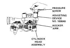
2.
Adjusting
Mount on cylin-
device No.
der head assembly.
100640
Turn pressure screw
until rocker arm
has been pushed
down 0.197 to
0.236 inch (5.0 to
6.0 mm).
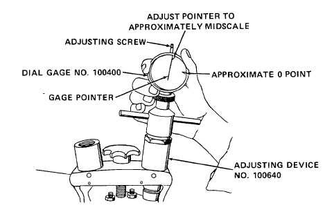
3.
Dial gage
Turn adjusting screw until gage pointer reads approxi-
No. 100400
mately midscale. Mount on adjusting device.
4.
Flywheel or
Rotate crankshaft as in step 1. Rotate slowly until
V-belt pulley
piston starts to push up valve. Gage pointer will move
up scale clockwise. Continue to rotate crankshaft un-
til gage pointer stops moving up scale/clockwise and
just starts to change direction to down scale/counter-
clockwise. Mark this point on gage as the 0 point.
6-7