TM 5-4320-302-14
CHAPTER 2
OPERATING INSTRUCTIONS
Section I. DESCRIPTION AND USE OF OPERATOR'S CONTROLS AND INDICATORS
WARNING
Personal injury may result if the engine is not turned off during service or maintenance.
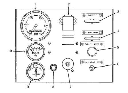
Table 2-1. Operator's Controls and Indicators
Control or
Key
Indicator
Function
1
Tachometer
Indicates engine speed in revolutions per minute (rpm) and elapsed
time in hours, tenths, and hundredths. Mechanically coupled to
rotating cable that is connected to the drive gear. Graduated in
100 rpm increments from 0 to 3500 rpm. The elapsed time meter
will record up to 9999.99 hours of operation.
2
Air cleaner intake
Indicates blockage of air filter. A red indication appears in window
restriction in-
to indicate the need for cleaning or replacement of elements.
dicator
Indicator is connected to air inlet housing by a flexible hose, and
is actuated by high negative pressure. Indicator can be reset.
3
Throttle T-handle
Push-pull cable. T-handle mechanically connected to throttle. Con-
trols engine speed. Coupled to speed control lever by a control wire.
Uses a mechanical lock. Pull throttle T-handle to increase engine
speed; push it in to decrease engine speed. Turn clockwise to lock.
2-1