
retaining ring. Use two pairs of pliers to
force thrust collar over ring.
(2) If brushes have been replaced, seat them
using No. 00 sandpaper before assembling
the end frame. Blow the brush particles off
the commutator so that they will not cause a
short circuit during operation.
(3)
Check the pinion clearance after
reassembly by connecting the starting motor
and a battery in the circuit. Disconnect the
motor field lead from the solenoid motor
terminal.
Caution
Insulate the motor field lead
carefully to avoid arcing during the
checking procedure.
(4) Momentarily touch the jumper lead from the
solenoid motor terminal to the motor frame.
This will shift the pinion into cranking
position. It will stay in this position until the
battery is disconnected.
(5)
Push the pinion back toward the
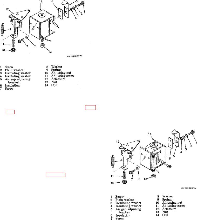
Figure 51. Voltage regulator, exploded view.
commutator end to eliminate all slack
movement. Measure the distance between
all particles off commutator using compressed
the pinion gear of the drive assembly (19)
air. Check armature for short circuits (para
and the retainer (18). If clearance is not
108c(6)).
between 0.010 and 0.140 inch, disassemble
Caution
the starting motor as described in b above,
Always blow particles off the
and
commutator in the direction away
from the armature windings.
(5) Check the brush holders for distortion,
cracks, breaks, or other damage; replace
damaged brush holders.
(6) Inspect the drive assembly for cracks,
breaks, clutching action, or other damage; replace the
drive assembly if any parts are damaged.
(7) Check the armature and field windings for
short circuits, grounds, and open circuits
using the same method described for the
generator parts (para 108
c). Replace the
starting motor if the armature of the field
windings is shorted, grounded, or open.
(8) If removed, replace the bushing in the drive
housing.
Replace the springs if brush
tension is not 24 to 28 ounces.
d. Assembly Assemble the starting motor in the
.
reverse order of disassembly. Observe the following
special instructions.
(1) Place the spring (21) and drive assembly
(19) on the shaft of the armature (15). Slide
Figure 52. Current regulator, exploded view.
the retainer (18) on the shaft with the
cupped side out. Force the retaining ring
(17) over the end of the shaft and position it
into the groove provided. Position the thrust
collar (16) on the shaft and against the
TAGO 6358A
66

