
TM 5-3825-270-23&P
0093
REMOVAL - Continued
5
6
3, 4
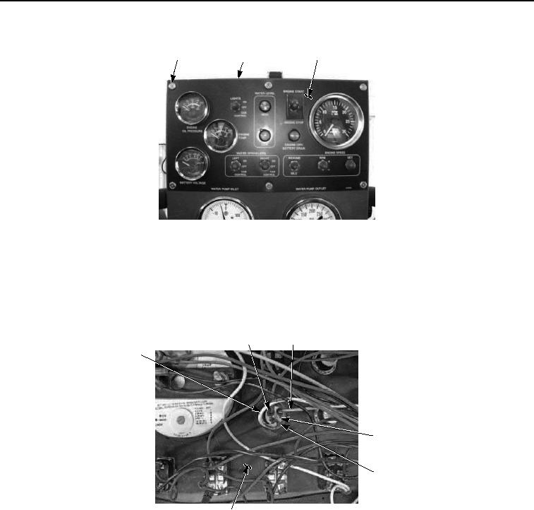
Figure 2. Main Control Panel Engine Off/Battery Drain Indicator Removal.
NOTE
Tag and mark wires prior to removal to ensure proper installation.
3.
Disconnect red wire (Figure 3, Item 8) and white wire with black stripe (Figure 3, Item 7) from main control
panel engine off/battery drain indicator (Figure 3, Item 10).
8
9
7
10
11, 12
6
Figure 3. Main Control Panel Engine Off/Battery Drain Indicator Removal.
4.
Disconnect white wire with red stripe (Figure 3, Item 9) from main control panel engine off/battery drain indicator
(Figure 3, item 10).
5.
Remove nut (Figure 3, Item 11), washer (Figure 3, item 12) and main control panel engine off/battery drain
indicator (Figure 3, Item 10) from control panel (Figure 3, Item 6).
END OF TASK
INSTALLATION
1.
Install main control panel engine off/battery drain indicator (Figure 4, Item 10) in control panel (Figure 4, Item
6) with washer (Figure 4, Item 12) and nut (Figure 4, Item 11).

