
TM 5-3825-270-23&P
0031
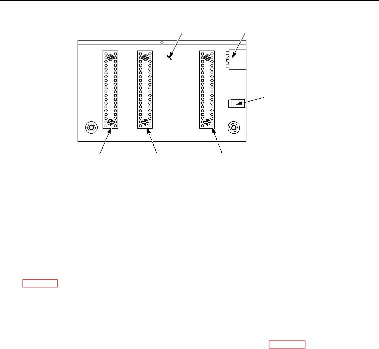
INSIDE OF
15-AMP
CONTROL PANEL
CIRCUIT BREAKER
20
1
1
15
5
5
EMERGENCY
10
10
10
STOP SWITCH
5
15
15
1
20
20
INTERCONNECT
POSITIVE
NEGATIVE
TERMINAL STRIP
TERMINAL STRIP
TERMINAL STRIP
Figure 2. Positive Terminal Strip - Step 2.
6.
Connect black multimeter lead to interconnect terminal strip, terminal 9.
7.
Note multimeter reading.
CONDITION/INDICATION
Are less than 200 ohms measured from positive terminal strip, terminal 15 to interconnect terminal strip, terminal
9?
DECISION
No - Repair or replace red wire from positive terminal strip, terminal 15 to interconnect terminal strip, terminal
9. (WP 0099) Verify problem is solved. (Step 5 - Does ENGINE OFF/BATTERY DRAIN indicator illuminate?)
Yes - Go to step 3. (Step 3 - Are less than 200 ohms measured on white/red stripe wire from ENGINE OFF/
BATTERY DRAIN indicator to governor controller harness connector, pin B3?)
STEP 3
Are less than 200 ohms measured on white/red stripe wire from ENGINE OFF/BATTERY DRAIN indicator to
governor controller harness connector, pin B3?
1.
Disconnect governor controller harness connector from governor controller. (WP 0092)
2.
Set multimeter to measure continuity.
3.
Connect red multimeter lead to white/red stripe wire on ENGINE OFF/BATTERY DRAIN indicator.

