
TM 10-4630-207-13&P
0027 00
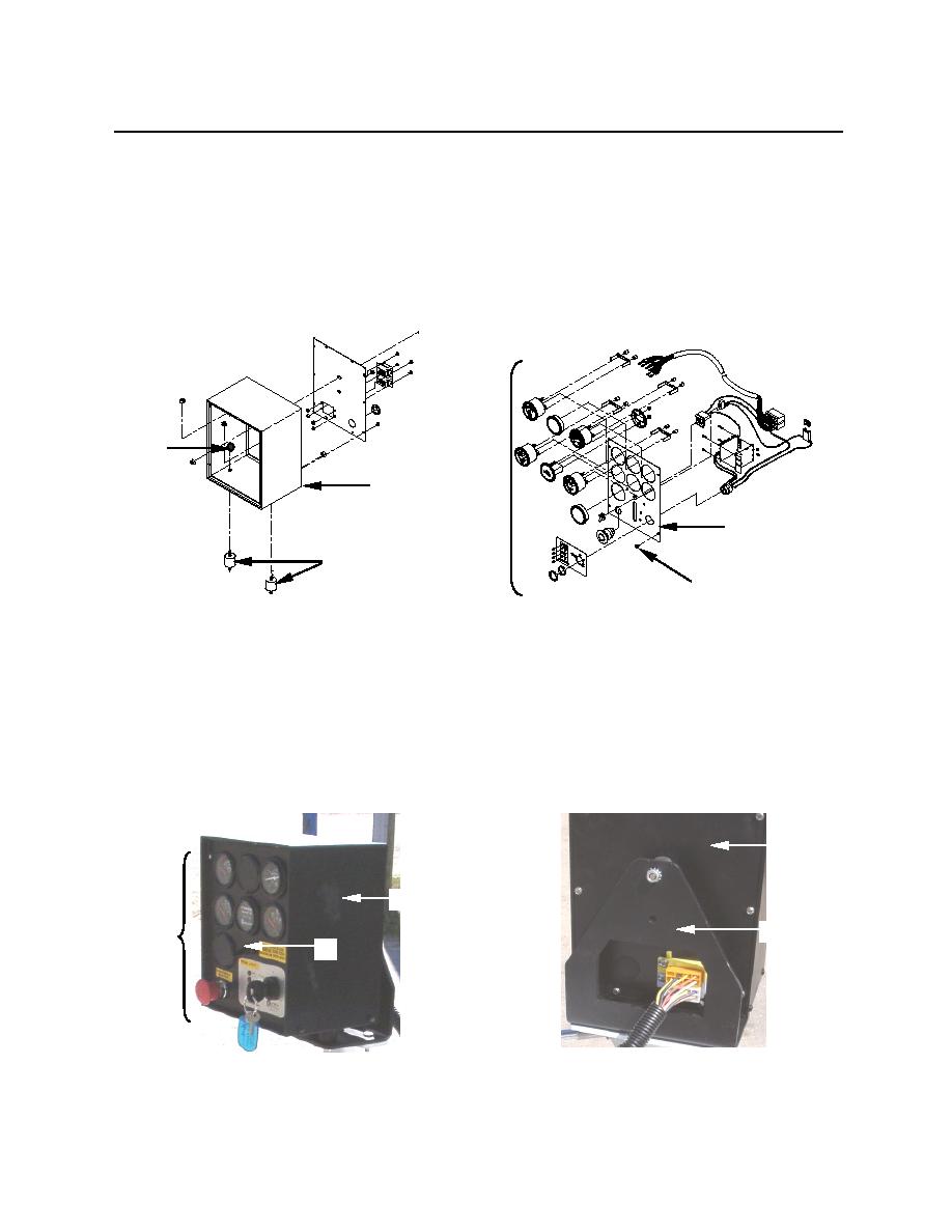
8. To remove the frontpanel (figure 6, item 1) from the enclosure (figure 6, item 2), remove four hex
screws (figure 6, item 3) that hold the panel to the enclosure.
9. If enclosure is being replaced, remove bottom isolation mounts (figure 6, item 4) from enclosure.
Retain hex nuts (figure 6, item 5).
NOTE
To remove the individual components (figure 6, item 6) mounted on the frontpanel, follow
the procedures under REPLACE, in this WP.
5
6
2
1
4
3
Figure 6. Removal of Frontpanel
10. Replace a bent, dented or otherwise damaged front panel (figure 7, item 5), backpanel (figure 7,
item 2), enclosure (figure 7, item 3), mounting bracket (figure 7, item 4) that cannot be repaired or
straightened out. Also replace deteriorated isolation mounts (figure 6, item 4),
NOTE
To install the components mounted to the front panel (figure 7, item 5), follow the
procedures under REPLACE, in this WP.
2
3
4
5
1
Figure 7. Control Panel Components
0027 00-4

