TM 10-4320-309-14
TM 4320-1 4/1
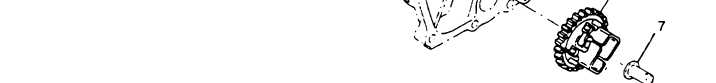
Figure 5-14. Lube Oil Pump Assembly
REMOVAL:
a.
Remove three lube oil pump cover bolts (6) holding lube oil pump cover (5).
b.
Remove lube oil pump cover (5).
c.
Remove O-ring (4).
d.
Lay crankcase cover on dean, flat surface.
e.
Grasp hold of the plastic gear and carefully pull spindle (7) and governor gear (3) from lube oil pump
shaft (1 B) and outer rotor (1A).
5-17